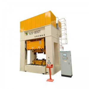
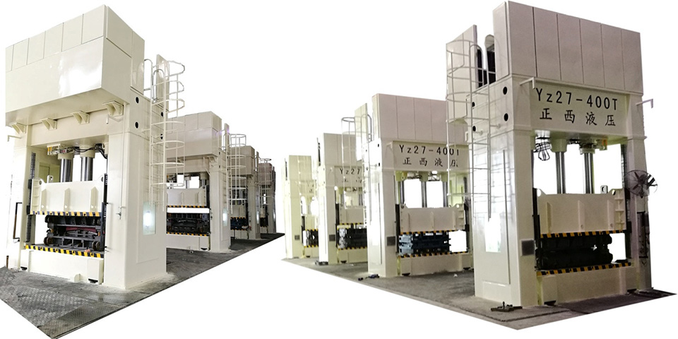
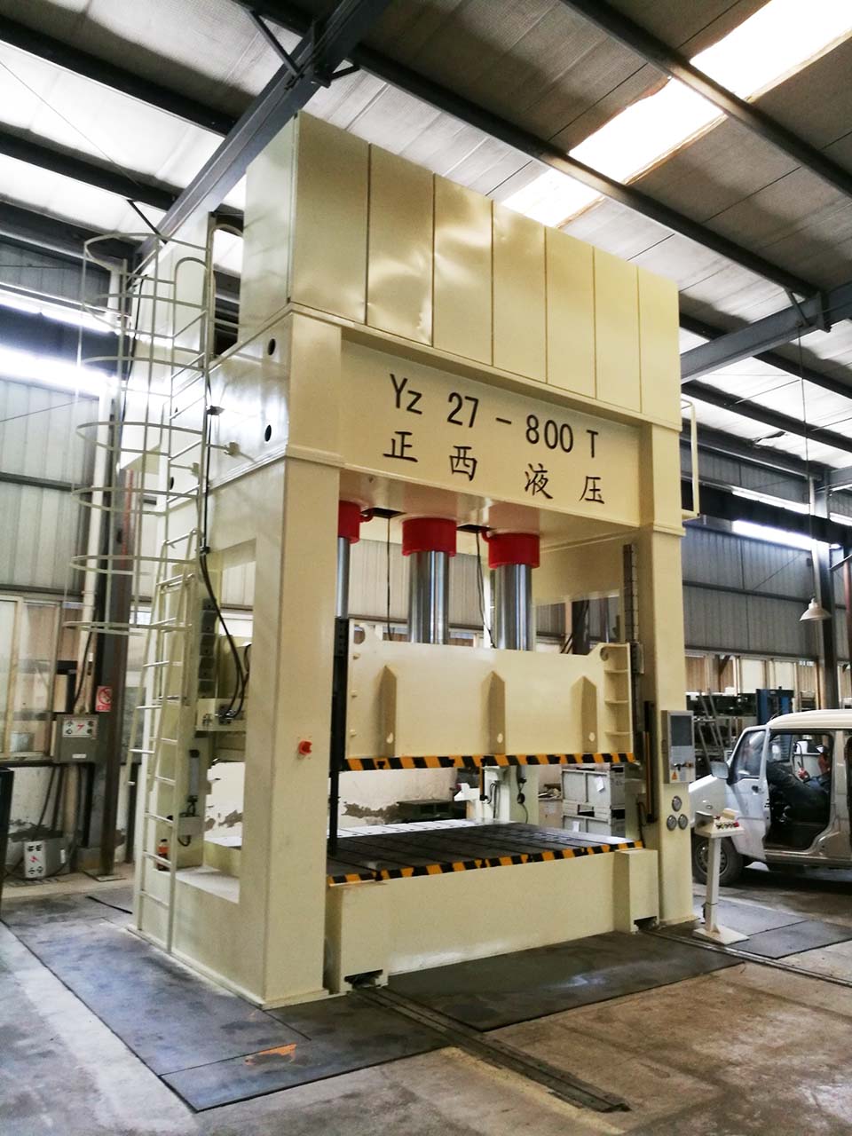
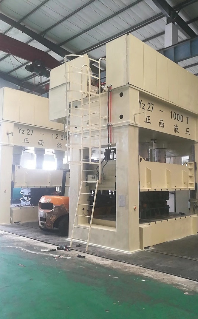
H frame metal deep drawing hydraulic press

H frame deep drawing press machine is mainly suitable for sheet metal part processes such as stretching, bending, crimping, forming, blanking, punching, correction, etc., and is mainly used for quick stretching and forming of sheet metal.
The press machine is been designed as assembled H-frame which has best system rigidity, high precision, long lifetime and high reliability, and is used for pressing sheet metal parts and can meet the demand of production at 3 shifts/day.

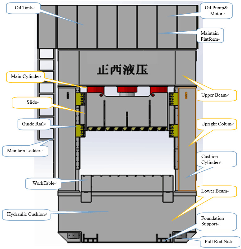
Structure and Composition
Machine Parameters
|
Name |
Unit |
Value |
Value |
Value |
Value |
|
|
Model |
|
Yz27-1250T |
Yz27-1000T |
Yz27-800T |
Yz27-200T |
|
|
Main cylinder pressure |
KN |
12500 |
1000 |
8000 |
2000 |
|
|
Die Cushion force |
KN |
4000 |
3000 |
2500 |
500 |
|
|
Max. liquid pressure |
MPa |
25 |
25 |
25 |
25 |
|
|
Daylight |
mm |
2200 |
2100 |
2100 |
1250 |
|
|
Main cylinder Stroke |
mm |
1200 |
1200 |
1200 |
800 |
|
|
Die Cushion Stroke |
mm |
350 |
350 |
350 |
250 |
|
|
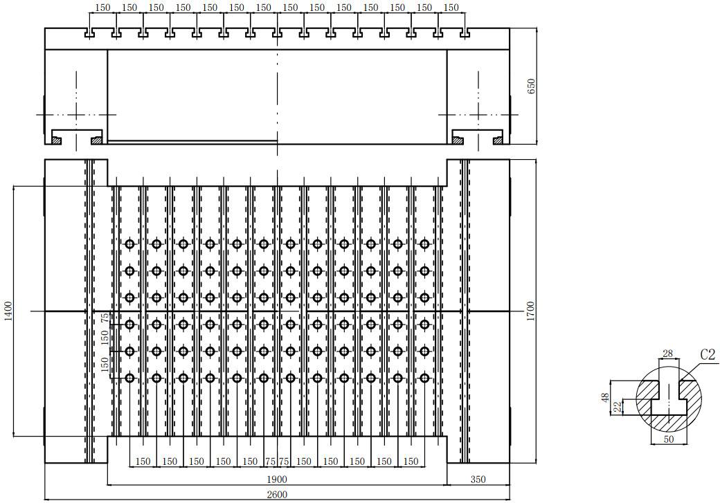
Worktable size
|
LR |
mm |
3500 |
3500 |
3500 |
2300 |
|
FB |
mm |
2250 |
2250 |
2250 |
1300 |
|
|
Die cushion size |
LR |
mm |
2620 |
2620 |
2620 |
1720 |
|
FB |
mm |
1720 |
1720 |
1720 |
1070 |
|
|
Slider speed |
Down |
mm/s |
500 |
500 |
500 |
200 |
|
Return |
mm/s |
300 |
300 |
300 |
150 |
|
|
Working |
mm/s |
10-35 |
10-35 |
10-35 |
10-20 |
|
|
Ejection speed |
Ejection |
mm/s |
55 |
55 |
55 |
50 |
|
Return |
mm/s |
80 |
80 |
80 |
60 |
|
|
Worktable moving distance |
mm |
2250 |
2250 |
2250 |
1300 |
|
|
Workbench load |
T |
40 |
40 |
40 |
20 |
|
|
Servo motor
|
Kw |
140 |
110 |
80+18 |
22 |
|
|
Weight of machine |
T |
130 |
110 |
90 |
20 |
|
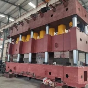
Die Cushion Details
Pillar
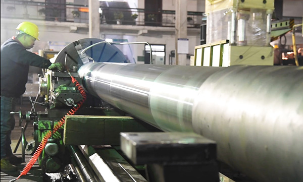
The guide columns (pillars) will be made of C45 hot forging steel and have a hard chrome coating thickness 0.08mm. And do hardening and tempering treatment. The guide sleeve adopts copper guide sleeve, which is more wear-resistant and improves the stability of the machine
Platen
The platen of this machine is welded by Q345B steel plate with a thickness of 120mm. The whole machine is heat treated to reduce welding stress and improve the stability of the machine. The platen surface is processed by a large grinder, and the flatness can reach 0.003mm.
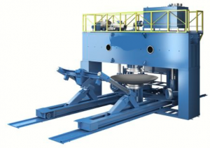
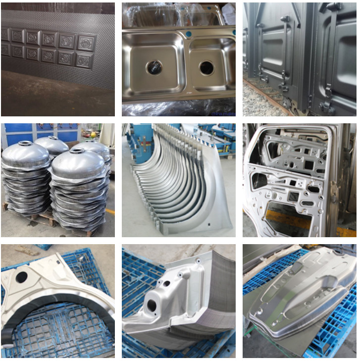
Similar Project
Application
Main Body
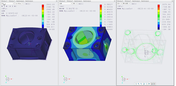
The design of the whole machine adopts computer optimization design and analyzes with finite element. The strength and rigidity of the equipment are good, and the appearance is good.
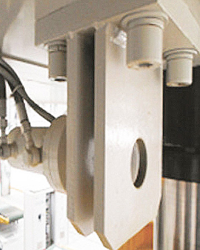
Cylinder
|
Parts |
Feature |
|
Cylinder Barrel |
Made by 45# forged steel, quenching and tempering
Fine grinding after rolling |
|
Piston Rod |
Made by 45# forged steel, quenching and tempering
The surface is rolled and then chrome-plated to ensure surface hardness above HRC48~55 Roughness≤ 0.8 |
|
Seals |
Adopt Japanese NOK brand quality sealing ring |
|
Piston |
Guided by copper plating, good wear resistance, ensuring long-term operation of the cylinder
|
Servo System
1.Servo System Composition
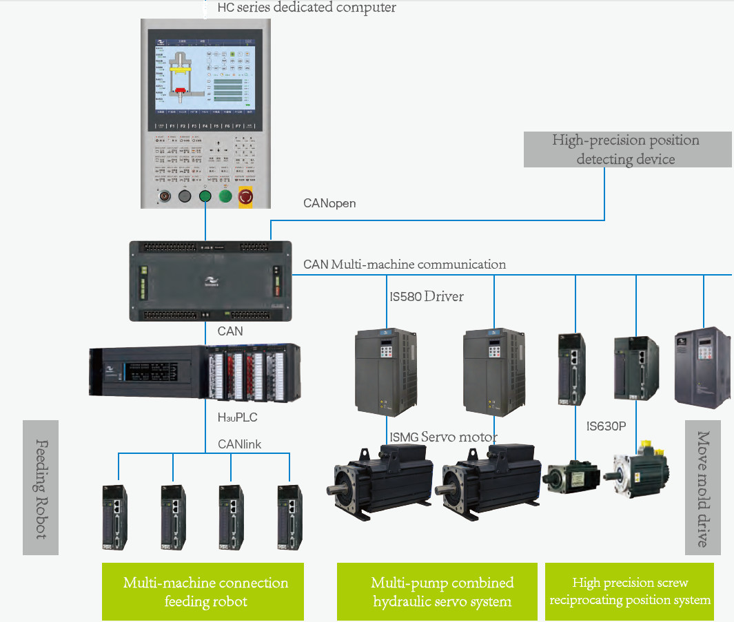
2.Servo System Composition
|
Name |
Model |
Picture |
Advantage |
|
HMI |
Siemens |
|
The life of the button is strictly tested, and it is not damaged by pressing 1 million times.
Screen and machine fault help, describe screen functions, explain machine alarms, and help users quickly master the machine usage
|
|
Name |
Model |
Picture |
Advantage |
|
PLC |
Siemens |

|
Electronic ruler acquisition line is processed independently, with strong anti-interference ability
Digital control of the servo drive and integration with the drive |
|
Servo Driver
|
YASKAWA |
|
The overall busbar capacitor is fully upgraded, and the capacitor with wider temperature adaptability and longer service life is used, and the theoretical life is increased by 4 times;
The response at 50Mpa is 50ms, the pressure overshoot is 1.5kgf, the pressure relief time is 60ms, and the pressure fluctuation is 0.5kgf.
|
|
Servo Motor
|
PHASE Series |
|
The simulation design is carried out by Ansoft software, and the electromagnetic performance is superior;Using high-performance NdFeB excitation, the iron loss is small, the efficiency is higher, and the heat is smaller;
|


3.Advantages of Servo System
Energy saving
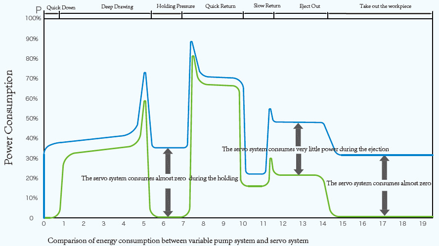
Compared with the traditional variable pump system, the servo oil pump system combines the fast stepless speed regulation characteristics of the servo motor and the self-regulating oil pressure characteristics of the hydraulic oil pump, which brings huge energy saving potential, and the energy saving rate can reach up to 30%-80%.
Efficient
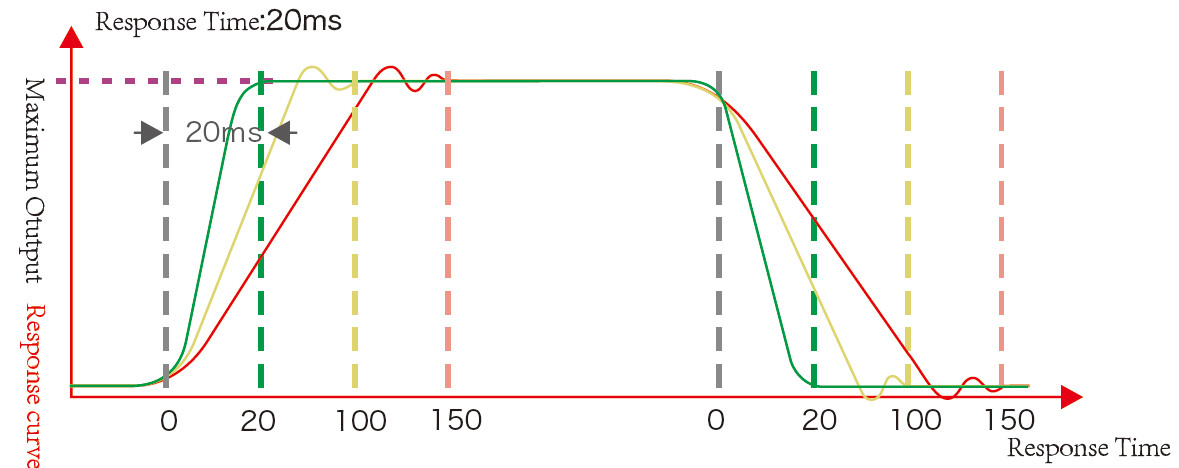
The response speed is fast and the response time is as short as 20ms, which improves the response speed of the hydraulic system.
Precision
The fast response speed guarantees the opening and closing accuracy, the position accuracy can reach 0.1mm, and the special function position positioning accuracy can reach ±0.01mm.
The high-precision, high-response PID algorithm module ensures stable system pressure and pressure fluctuations of less than ±0.5 bar, improving product quality.
Environmental protection
Noise: The average noise of the hydraulic servo system is 15-20 dB lower than that of the original variable pump.
Temperature: After the servo system is used, the hydraulic oil temperature is reduced overall, which enhances the life of the hydraulic seal or reduces the power of the cooler.
Safety Device
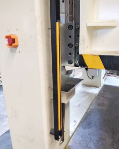
Photo-Electrical Safety Guard Front & Rear
Slide Locking at TDC
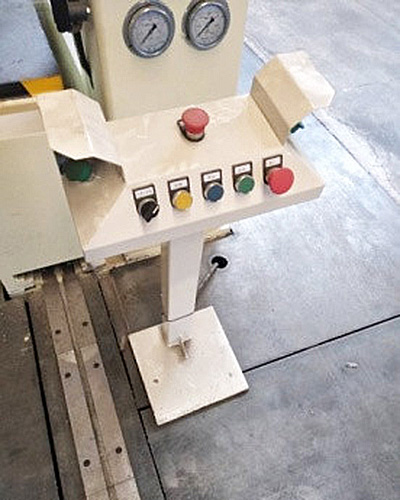
Two Hand Operation Stand
Hydraulic Support Insurance Circuit
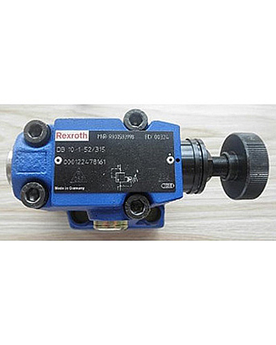
Overload Protection: Safety Valve
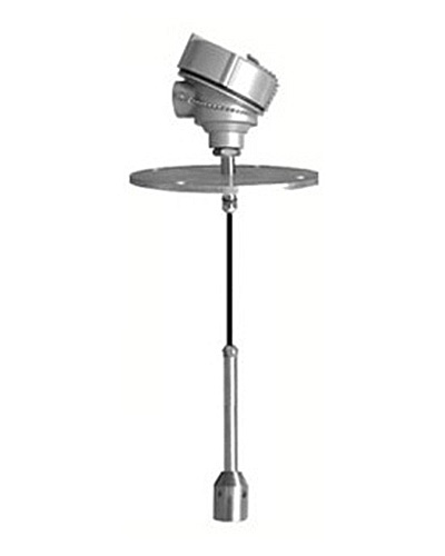
Liquid Level Alarm: Oil level
Oil temperature Warning
Each electrical part have overload protection
Safety blocks
Lock nuts are provided for movable parts
All action of press have safety interlock function, e.g. movable worktable will not work unless cushion return to initial position. Slide can not press when movable worktable is pressing. When conflict operation happen, alarm shows on touch screen and show what's the conflict.
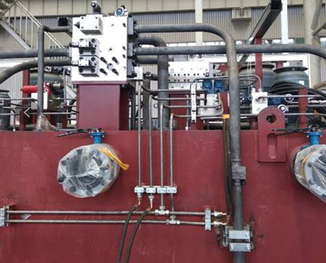
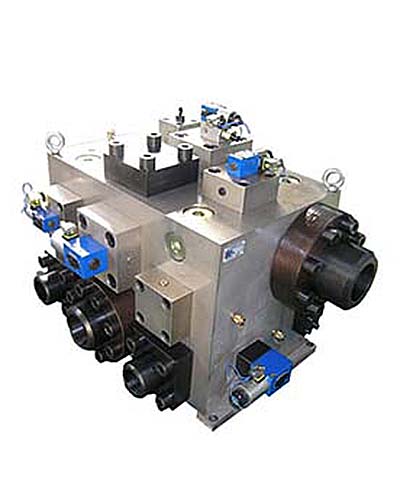
Hydraulic System
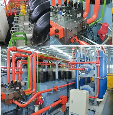
Feature
1.Oil tank been set forced cooling filtering system(industrial plate-type water cooling device, cooling by circulating water, oil temperature≤55℃,make sure machine can steadily pressing in 24 hours.)
2.The hydraulic system adopts integrated cartridge valve control system with fast response speed and high transmission efficiency.
3.The oil tank is equipped with an air filter to communicate with the outside to ensure that the hydraulic oil is not polluted.
4.The connection between the filling valve and the fuel tank uses a flexible joint to prevent vibration from being transmitted to the fuel tank and completely solve the problem of oil leakage.